

In a beer, blood, blades and gold paint orgy - on a rather chilly night- I was cut into the Puddle Cutters Moped Gang. I'd like to say it was a long, hard road, but it was actually a super fun time and I love the poodle cuties! As it happens, this is a Rally year here in Portland and the Puddle Cutters are hosting (August 9-11th). It's not going to be epic because that's kind of a tired term at this point. It's going to be a singularity of good times. <--- & that is now the dorkiest thing I've said in a month. And Star Trek just came out, so....
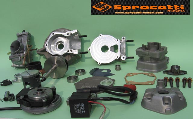
In actual moped news, I've been working on another very modified vespa engine, mostly as an experiment. As we all know, reed valve induction is effectively the best kind, for lots of reasons. They are cheap to build, easy to repair, performance is excellent and they don't interfere with other aspects of operation. But as an academic point, Rotary valve is the most powerful induction method. Albeit by ever thinner margins - and if you doubt - may I point to all of the fastest MotoGP bikes before FIM killed two-strokes in MotoGP. - many of which use round-slide carbs..Whaaaa...? So basically I got to thinking that unless you can somehow obtain a $$$$procatti complete engine, fast rotary valve mopeds just don't exist and I want to try(?!)
What limits the stock Vespa moped engine to sucking at life is the quite small carb flange (11.5mm ID) coupled with a tiny rotary pad. A crankshaft with a larger cut-out increases the intake timing duration, but fitting a larger carburetor is pointless without a racing engine case. Furthermore, the precise timing of the intake duration's opening and closing points increases horsepower and fattens the powerband. (I need a bigger hole, and I need it in exactly the right spot) So I took a stock vespa engine case and very carefully plotted the stock crank cut-out and position of the rotary pad and opening. I decided that a few things were too difficult to modify so my solution would have to fall in between the existing case bolt holes (51mm) and use the stock thickness of the crank web as parameters. As it turns out the piaggio engineers placed the stock crank cut out and rotary pad in a very good spot for modification. My goals were two:
1. Optimize the intake timing to account for both duration and exact positioning2. Create a suitable mount to operate a larger carburetor
I settled on 205 degrees total duration for the rpm's I'm shooting for with 68 degrees BTDC & 137 degrees ATDC (or vice-versa, i don't have my notes with me). Once I had my plan, I welded some fat blobs of aluminum up against the existing rotary pad. I'm still thankful for the well positioned stock inlet. Welding on old old-soaked cast aluminum SUCKS. But I got it done.

After adding meat to the rotary pad, I built a alignment/centering jig and set up a bore-bar to cut down the excess aluminum back to stock tolerances. With that large of a diameter it was a kind-of terrifying tool to use.

I chose to build up the thickness of the case on the opposite of the rotary pad, so that I could weld a substantial enough block to support two 6mm threadings and the manifold that will eventually attach there. This extra thickness also enables a more aerodynamic transition from the round carburetor bore to the rectangular opening on the rotary pad. So I welded some (alot) more on this G'Danged cast aluminum. It still sucked. Then I milled down that mess into a usable flat surface I could weld the intake/mounting block onto.

 That weird hole is the stock intake as revealed by the milling I've done. If you're curious, the reason for the bolts still being in the case, is that they act like heat-sinks when welding Aluminum, which helps -also if I got it waaay too hot, it could potentially prevent major distortion.
I then fabb'ed the intake block, making it capable of flowing a 21mm carb. I believe that to be the biggest possible with this set-up, due to the limitations imposed by the case bolt-holes and crank web-thickness (as mentioned previously). The rectangular hole is precisely 7mm wide and 38.5mm long on the rotary pad. Next up is some final filing and porting of the block and then to weld that sucker to the case. The porting revealed a very thin spot in the casting, which will have to be filled in from the stator plate side. (not pictured) The weld along the case-halves will need to be cleaned up as well. Afterwards, I will need to create a manifold that can attach a carb and shoehorn into the small void behind the motor in a conventional Vespa subframe. I've mocked this up, and anticipate only mild difficulty.

 I also welded up that Plug Nut to the Puch Maxi / SwampThing exhaust and built up the flamethrower periphery. I need to work out the stoichiometry, as presently I am getting no flames, just copious amounts of smoke. Any advice?? But as they say, where there's smoke, there's an idiot with a moped flamethrower exhaust. I need to mill the cylinder head surface on my swamp thing cylinder, as a minor flaw is causing an airleak and preventing me from actually riding that beast around. FINALLY.


Presently these projects are on standby, due to a safety violation (working alone) at my workspace getting my shop privledges suspended :( Hopefully that will get rectified soon, and I will have more to report on my stupid projects! Thanks for reading!!